SMT Solder Paste Manufacturers.

Focused on SMT soldering processes, a one-stop electronic soldering solutions provider.

Here you can find knowledge about SMT Solder, including but not limited to usage methods, installation techniques, troubleshooting and more. Focused on SMT soldering processes. If you can't find what you need, please contact us anytime.
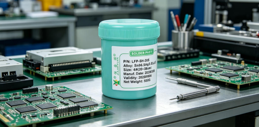
Based on 20 years of frontline SMT debugging experience, this paper analyzes the actual impact of key solder paste printing parameters such as printing speed and pressure on yield, identifies three major trends under high-speed printing: the narrowing of the fine-tuning window for squeegee pressure, accelerated attenuation of stencil life, and intensified shear thinning of solder paste, reveals the dual driving logic of equipment aging and the popularization of new fine-pitch devices, and provides practical SMT debugging recommendations for production line engineers, including the mandatory simultaneous monitoring of SPI data and squeegee wear status, and the incorporation of printing speed gradient testing into the standard line changeover process.
Published: 2026-08-27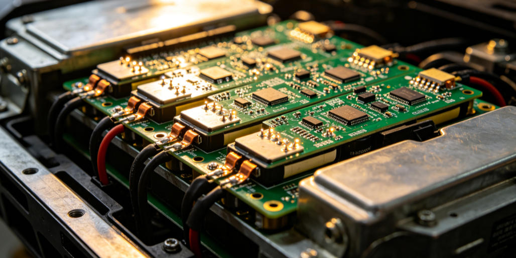
SMT soldering of thick copper boards is prone to cold solder joints and insufficient soldering due to their large heat capacity and delayed temperature rise. Solder paste activity matching and precise control of the reflow temperature profile are required to ensure solder joint reliability. The ramp-up rate in the preheating zone must be controlled between 0.5℃/s and 1.5℃/s, and the peak temperature must meet the component class limits specified in IPC-J-STD-020D. Otherwise, batch failures such as solder balls, tombstoning, and PCB delamination will occur.
Published: 2026-08-27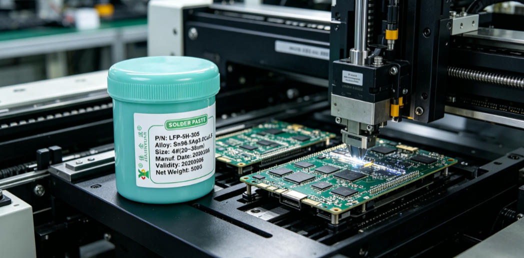
In the double-sided mounting process, the solder paste soldering reliability of the second reflow pass is highly dependent on printing accuracy, reflow profile matching, and component heat capacity coordination. Based on measured data from mass production lines, this paper explicitly specifies key parameters including a stencil thickness of 0.12mm, a squeegee pressure of 2.8kg, and a reflow peak temperature of 235℃±2℃, and points out that the risk of re-melting of already soldered components on the A side during the B-side reflow pass is concentrated on resistors and capacitors below 0603 and the bottom pads of QFN packages.
Published: 2026-08-27
The SMT solder paste cleaning process must be precisely matched to the solder paste type. Although no-clean solder paste is nominally described as requiring no cleaning, the risk of ionic residue still needs to be evaluated in high-reliability scenarios. Water-washable solder paste, by contrast, must be paired with a complete cleaning process such as deionized water spraying, ultrasonic cleaning, or brushing. The two types differ fundamentally in cleaning equipment selection, water quality control, and residue inspection.
Published: 2026-08-27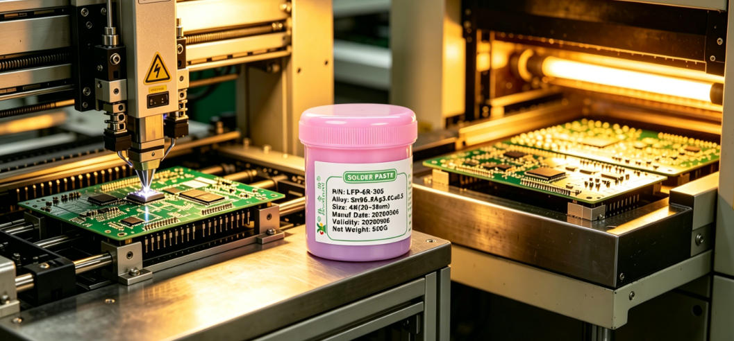
Reflow profile adjustment during SMT soldering with halogen-free solder paste is a core factor affecting solder joint reliability and defect rates. Based on 20 years of practical production line experience, this paper directly addresses common high-frequency issues such as solder balls, tombstoning, and poor wetting. Focusing on four key variables—heating rate, soaking time, peak temperature, and cooling rate—it provides immediately actionable parameter fine-tuning solutions and error-prevention guidelines.
Published: 2026-08-27
The selection of SMT stencil thickness is shifting from experience-driven to solder paste alloy property adaptation-driven. Lead-free high-melting-point alloys have pushed the proportion of ultra-thin stencils below 0.12mm to 38%, while low-temperature solder paste has shown a 12% increase in collapse rate on 0.15mm stencils in production line measurements. Process engineers need to dynamically adjust stencil thickness based on three key factors: alloy melting point, powder particle size, and flux activity.
Published: 2026-08-27
Abnormal solder paste viscosity during SMT soldering of fine-pitch chips can lead to typical defects such as solder bridging, insufficient solder, and misalignment. Based on real production line fault scenarios, this paper analyzes the causal chain between solder paste viscosity fluctuations and mismatched stencil printing parameters, and provides emergency and fundamental solutions including fine-tuning of squeegee pressure, environmental temperature and humidity control, and standardization of solder paste warm-up and stirring.
Published: 2026-08-27
Solder paste mixing and solder paste warming are hidden cost black holes in SMT production lines. Standardized operations can reduce solder paste scrap rate by 12%, reduce printing defect rate by 3.8%, and extend stencil life by 20%. Based on 20 years of production line measured data, this article provides 6 immediately executable cost-reduction actions, covering real scenarios such as warming time control, mixing method switching, environmental temperature and humidity linkage, and batch management optimization.
Published: 2026-08-27
The soldering quality of QFN is highly dependent on the coordinated control of SMT stencil aperture design and reflow process parameters. IPC-7525B explicitly requires that the pad aperture area ratio be no less than 0.66, and the optimal range in actual production lines is 0.72~0.78. A ratio below 0.62 will cause the cold solder joint rate to rise sharply by more than 12%. If the reflow peak temperature deviates from the 260℃±5℃ range specified in JEDEC J-STD-020, the void rate of QFN bottom solder joints may exceed the Level 3 limit of 25% stipulated in IPC-A-610E.
Published: 2026-08-27
Manual SMT rework soldering must precisely match solder wire diameter, soldering iron power, and actual soldering temperature; otherwise, cold solder joints, pad peeling, or thermal damage to components are highly likely to occur. Based on high-frequency production line fault cases, this paper compares the differences in temperature response curves, wetting speed, and solder joint morphology between 0.3mm and 0.5mm solder wires in typical scenarios such as QFN16, 0402 resistors, and shield can three-point grounding. It clearly points out that 0.3mm solder wire paired with a 35W soldering iron at 280℃ is more suitable for precision component rework soldering, while 0.5mm solder wire requires a soldering iron of 50W or above set at 320℃ to ensure the heat conduction efficiency of large pads.
Published: 2026-08-27Our technical team is always ready to provide professional solder material selection advice and SMT process solutions.