SMT Solder Paste Manufacturers.

Focused on SMT soldering processes, a one-stop electronic soldering solutions provider.

Here you can find knowledge about Solder Paste, including but not limited to usage methods, installation techniques, troubleshooting and more. Focused on SMT soldering processes. If you can't find what you need, please contact us anytime.

Although no-clean solder paste eliminates the cleaning process in SMT soldering, post-soldering residues can easily cause poor ICT probe contact, false judgments in flying probe testing, and missed detections in functional testing. Based on production line measured data, this paper proposes 6 actionable cost-reduction measures covering solder paste selection, stencil design, reflow parameters, and test fixture maintenance, which can reduce annual test misjudgment working hours by 1200 hours and reduce false rework costs by 84,000 yuan per plant.
Published: 2026-08-27
Improper temperature setting of the wave soldering pot is one of the main causes of cold solder joints, bridging, and poor wetting. There are significant differences in melting point and activity among different solder bar alloys. The wave soldering pot temperature must be accurately set according to the actual type of solder bar alloy used; otherwise, it can easily cause batch soldering defects.
Published: 2026-08-27
Addressing the widespread issue of excessive solder paste voids in high-thermal-dissipation PCBs during SMT reflow soldering, this paper draws on 20 years of practical production line experience to systematically outline 6 types of high-frequency failure phenomena. These cover real-world causes including heat sink design defects, mismatched stencil apertures, improper solder paste selection, uncontrolled printing parameters, imbalanced reflow profiles, and fluctuating nitrogen purity. For each cause, immediately actionable calibration steps and routine preventive measures are provided, directly targeting the core process bottlenecks for SMT void improvement in high-thermal-dissipation PCBs.
Published: 2026-08-27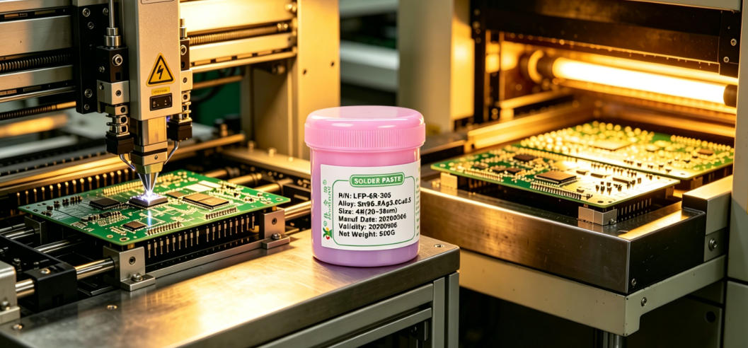
Solder paste warehouse management in SMT workshops is shifting from static temperature control to dynamic lifecycle tracking. Trends such as linked environmental temperature and humidity alarms, automatic timing of open-container duration, and batch-level modeling of thermal cycling-induced degradation are driving the upgrade of warehouse systems. Refined control of solder paste warehouse management has become the primary frontline defense to reduce soldering defects such as cold solder joints, tombstoning, and solder balls.
Published: 2026-08-27
In BGA rework, the amount of solder paste used and hot air temperature control directly determine solder joint reliability. The IPC-7711/21C standard explicitly requires that the deviation of solder paste volume must not exceed ±15%, and the reflow peak temperature must be controlled within the range of 235℃±5℃. Excessive temperature easily causes PCB delamination and chip cracking, while excessive solder paste leads to bridging and excessive void rate. In front-line practical operations, parameters need to be dynamically adjusted in combination with stencil thickness, chip solder ball diameter, and PCB copper foil density.
Published: 2026-08-27
In the mixed assembly board SMT process, the combined use of solder paste and manual solder wire can easily cause hidden defects such as cold solder joints, bridging, and thermal damage. Based on 20 years of practical production line experience, this article directly addresses five high-frequency pitfalls in the mixed use of solder paste and solder wire: improper stencil aperture design, conflicting reflow temperature windows, mismatched manual repair soldering timing, misjudgment of flux compatibility, and uncontrolled thermal stress superposition. Each pitfall includes its symptoms, hazards, root causes, and countermeasures, avoiding the substitution of theory for on-site judgment.
Published: 2026-08-27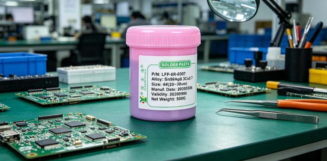
In high-current terminal welding, improper solder wire selection and uncontrolled soldering iron temperature commonly cause cold solder joints, dry solder joints, or thermal damage to terminal base materials. This article directly addresses real-world misconceptions on production lines, covering six major pitfalls including flux residue corrosion, mismatched wire diameters with solder wire specifications, and temperature settings that ignore heat capacity differences. It emphasizes that terminal welding must reverse-engineer solder wire activity grade and diameter based on current-carrying capacity, and dynamically adjust soldering iron temperature according to terminal material thickness.
Published: 2026-08-27
SMT for automotive industrial control boards has extremely high requirements for soldering reliability; even minor deviations in solder paste control can trigger batch defects such as cold solder joints, solder bridges, and tombstoning. This article directly addresses real-world misconceptions on the production line, covering five high-incidence issues: temperature control failure during solder paste storage, insufficient reflow time, mismatched squeegee pressure, mismatch between stencil aperture design and solder paste particle size, and excessive dwell time after printing. Each point is derived from measured failure cases, emphasizing that solder paste control in industrial control board SMT must run through the entire process from material requisition to component placement.
Published: 2026-08-27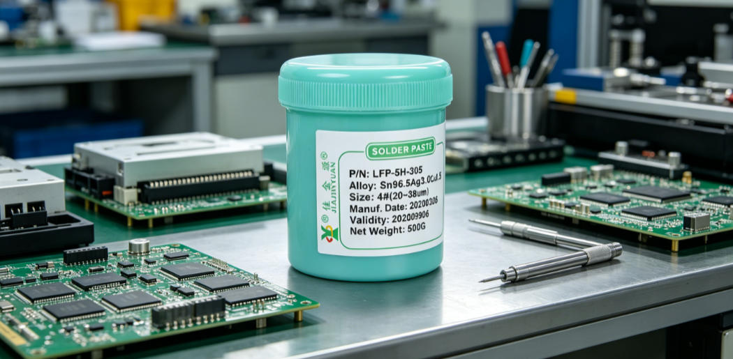
Based on 20 years of frontline SMT debugging experience, this paper analyzes the actual impact of key solder paste printing parameters such as printing speed and pressure on yield, identifies three major trends under high-speed printing: the narrowing of the fine-tuning window for squeegee pressure, accelerated attenuation of stencil life, and intensified shear thinning of solder paste, reveals the dual driving logic of equipment aging and the popularization of new fine-pitch devices, and provides practical SMT debugging recommendations for production line engineers, including the mandatory simultaneous monitoring of SPI data and squeegee wear status, and the incorporation of printing speed gradient testing into the standard line changeover process.
Published: 2026-08-27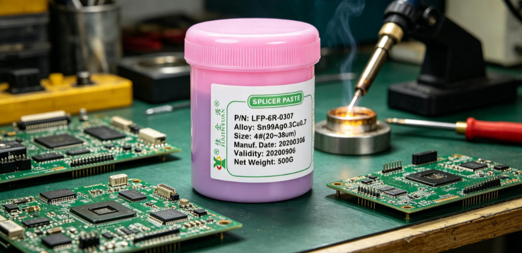
The compatibility between wave soldering flux and solder bars directly affects solder joint gloss, wetting uniformity, and residue morphology. Based on production line measured data, this paper horizontally compares the combined performance of three types of fluxes—rosin-based, no-clean, and water-soluble—paired with 63/37, 60/40, and SAC305 solder bars respectively. The analysis is conducted from four dimensions: wetting angle variation, solder joint reflectivity, bridging occurrence rate, and cleaning difficulty. It is clarified that for scenarios requiring high gloss, rosin-based flux paired with 63/37 solder bars is preferred, while for high reliability requirements, water-soluble flux paired with SAC305 is favored.
Published: 2026-08-27Our technical team is always ready to provide professional solder material selection advice and SMT process solutions.