SMT Solder Paste Manufacturers.

Focused on SMT soldering processes, a one-stop electronic soldering solutions provider.

Here you can find knowledge about Solder Storage Conditions, including but not limited to usage methods, installation techniques, troubleshooting and more. Focused on SMT soldering processes. If you can't find what you need, please contact us anytime.
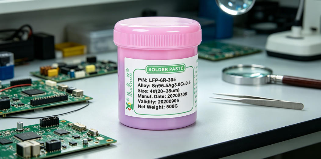
Aiming at typical defects such as solder joint blackening, cold solder joints, and stencil clogging caused by solder paste and solder bar switching during the lead-free to leaded transition in the SMT line changeover process, this paper, based on real production line cases, details rapid response actions including emergency line shutdown and cleaning, flux residue removal, and equipment pipeline passivation treatment, and proposes root-cause elimination measures such as solder paste zoning management, solder bar batch binding, and dynamic monitoring of reflow oven nitrogen purity, providing an immediately executable closed-loop solder paste and solder bar switching process for SMT line changeover.
Published: 2026-08-27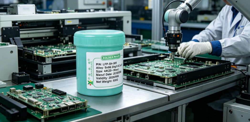
To address the frequent solder bridging and solder spike defects of large-size QFP devices in the SMT process, this paper starts from solder paste selection, and combines printing accuracy, reflow thermal response and metal powder distribution characteristics to elaborate on special solder pastes with high thixotropy, narrow particle size distribution (D50=18.5μm) and 90.2% metal content, such as
Published: 2026-08-27
The control of the solder wire feeding angle directly affects the spatter rate of manual soldering. The industry is currently accelerating its evolution toward micro-solder joints below 0.3mm, high-density mixed-assembly PCBs, and lead-free high-temperature processes. However, the traditional fixed 45° solder feeding method can no longer match the production line reality where 0.25mm pitch QFNs and 0402 components coexist. Frontline engineers must dynamically compress the angle between the solder wire and the soldering iron tip to the 25°~35° range, while synchronously adjusting the solder feeding rhythm and the soldering iron withdrawal timing.
Published: 2026-08-27
Restarting the machine after an SMT shutdown involves multiple risks such as reduced solder paste printing accuracy, stencil clogging, and solder paste activity attenuation. Differentiated response strategies must be developed based on the shutdown duration, ambient temperature and humidity, and solder paste type, with particular attention paid to squeegee pressure calibration, stencil cleaning frequency, and solder paste rewarming and stirring operations in the solder paste printing process.
Published: 2026-08-27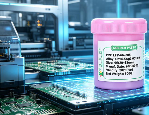
Poor solder paste wettability during SMT soldering on thick gold PCBs commonly manifests as solder joint voids, insufficient solder climb, or local dewetting. The root cause is excessive gold layer thickness leading to nickel layer passivation and excessive consumption of flux activity. Evaluation requires comprehensive judgment by combining wetting angle measurement, microscopic observation of solder joint morphology, and IMC growth state after reflow. The matching between thick gold PCBs and solder paste wettability is a key process control point to ensure first-pass yield.
Published: 2026-08-27
How to select solder paste for SMT must be based on actual production line failures to reverse-engineer process adaptability. Lead-containing solder paste is easy to solder but restricted by RoHS; lead-free solder paste has a high reflow temperature, which easily causes BGA cold solder joints and PCB blistering; halogen-free solder paste, while solving halogen corrosion, sacrifices part of its wettability. The core of solder paste selection lies in matching equipment capabilities, component temperature resistance windows, and long-term reliability requirements. Especially for halogen-free solder paste applications in high-temperature and high-humidity environments, stencil aperture and reflow profile need to be adjusted simultaneously.
Published: 2026-08-27
Solder selection directly affects SMT first-pass yield and rework costs; solder paste, solder wire, and solder bars must be dynamically matched according to process takt, solder joint precision, and rework frequency. For example, batch mounting of 0201 components requires 3# powder solder paste paired with stainless steel stencils, while bottom rework for BGA preferentially uses 0.3mm diameter no-clean solder wire, saving over 240 hours of rework labor per production line annually.
Published: 2026-08-27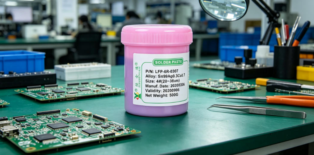
The SAC305 and Sn99.3Cu0.7 solder paste alloys exhibit significant differences in actual SMT production lines. SAC305 has better wettability and thermal fatigue resistance, while Sn99.3Cu0.7 offers lower cost and a narrower melting range window due to its silver-free composition. For both alloys, dynamic trade-offs must be made in terms of printability, reflow void rate, solder joint strength, and long-term reliability, taking into account specific component types, board thickness, and reflow oven temperature zone configuration.
Published: 2026-08-27
The viscosity and thixotropic index of solder paste directly affect SMT printing accuracy and solder joint yield. IPC-J-STD-005 specifies that the viscosity range of solder paste is 200–800 Pa·s (25℃), and the thixotropic index should be ≥0.75. When the measured value is below 0.65, it is easy to cause solder spikes, bridging and insufficient solder; when it is above 0.95, it will lead to poor demolding and edge collapse. The production line needs to conduct actual measurement and temperature calibration every 4 hours using a Brookfield LVDV-II+ with matching cone-and-plate rotors to avoid data drift caused by an ambient temperature difference exceeding ±2℃.
Published: 2026-08-27
The classification of solder wire flux types must strictly align with the activity grades, halogen content, and residue cleanability requirements for rosin-based, no-clean, and water-soluble fluxes specified in the IPC J-STD-004B standard. Although water-soluble fluxes offer the advantages of high activity and easy cleaning, they carry a risk of chloride ion residue exceeding the 2.5μg/cm2 limit. If the production line fails to implement the deionized water rinsing process specified in IEC 61189-2, it will easily lead to PCBA corrosion failure.
Published: 2026-08-27Our technical team is always ready to provide professional solder material selection advice and SMT process solutions.