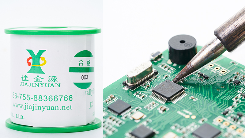
When choosing the type of welding material, attention should not only be paid to the mechanical properties of the welding material itself, but also to the reliability of the weld point formed by the welding material. In fact, the mechanical properties of soldering materials are not entirely equivalent to those of solder joints, especially for lead-free solder joints. A solder joint is formed at the connection between the solder and the solder padMCTin-lead solderMCThe mechanical strength is greater than the strength of the solder itself. When subjected to external force impact, fracture usually occurs through the solder itself, and at this time, external force impact energy is required. The solder joints produced by lead-free solder are different and will break under high-speed impactIMCWith the acceleration of the impact velocity,IMCThe probability of fracture will also increase, and no overly strong external impact energy is required. Therefore, major manufacturers are increasingly attaching importance to the solder joint tests of lead-free solders. Through these testsLead-free solder wireEvaluate its mechanical properties. The solder paste manufacturer will explain the review for everyone:
I. High-temperature aging method:
High-temperature aging method is a commonly used experimental method, which is simple and reliable. Generally speaking, the performance of solder joints will decline after aging. The degree of degradation of solder joint performance varies among different solders. The specific method is to put the sample into the oven for aging The oven temperature can be selected150/180/2000℃,200/300/400hThen test the strength of the solder joints and select good solder through comparison.
Ii. High-speed Impact Test of Solder joints:
Although we focus on brittle fracture caused by lead-free soldering, it is not common for brittle fracture failure to occur due to early cutting and tensile test methods. This is not because brittle fracture does not occur, but simply because the early test system cannot provide a stable force to prove the existence of this failure mode.
In recent years, engineers have developed high-speed impact test systems for solder joints to simplify the tests.
Iii. Drop Test: Drop test is one of the traditional methods for evaluating the reliability of solder joints. It is simple and easy to implement with low cost.
At present, it is mainly used to evaluate electronic products that are easy to implement, such as portable electronic products like mobile phones. Because this type of product is very likely to fall to the ground during use and may cause electrical malfunctions, including the cracking of solder joints between components and circuit boards. In addition, drop tests can also be used for comparative tests, such as lead-free tests WLCSPWhen the components undergo drop tests, the reliability of the solder joints can be compared between those with bottom filler and those without bottom filler. Usually, lead-free solder joints with bottom filler are found WLCSPThe component has good reliability.
Drop tests can be referred toGB2423And JEDEC JESD22-B111Proceed in a standard manner.
Iv. Board-level testing The solder to be evaluated is assembled into a test board (usually different solder comparison tests are conducted), and then the test method of high and low temperature impact method is selected as needed. The high and low temperature shock method can be carried out in accordance with the following standards:
●IPC-SM-785"Guide for Accelerated Reliability Testing of Surface-mounted Welded Parts"
●IPC-9701"Accelerated Reliability Test Methods and Qualification Requirements for Surface-mounted Welded Parts"
●IPC-TM-650"Manual of Experimental Methods"
The specific method is to place the welding sample in a dedicated high and low temperature test chamber.IPC-9701Five performance test methods are set under the test conditions in the standard, with relatively low requirementsT100℃It's very strictT180℃CThe plan is divided into five different levels. The greater the temperature difference, the worse the conditions, and the higher the reliability requirements for the solder joints.
Stay at both low and high temperatures30One standardminEach change is a cycle. Usually, a test requires2Ten thousand times~3000One cycle, and then through visual inspection or compression IPC-TM6650Standard test evaluation.5The temperature differences of different grades are:
●TC1:0℃/30min←→100℃,Tfor100℃Recommended for reference;
●TC2:-25℃/30min←→100/30min,Tfor125℃;
●TC3:-40/30min←→125/30min,Tfor165℃;
●TC4:-55/30min←→100C/30min,Tfor155℃;
●TC5:-55/30min←→125℃/30min,Tfor180℃
Conduct the test as follows:
Cracking incidence rate per100Make a judgment once per cycle;
Peel strength per500Test once in a cycle.
The above-mentioned test imitates the working state of electronic products. That is, due to their own resistance, the solder joints return to room temperature when current passes through. The change from high temperature to room temperature means that the solder joints undergo changes in high and low temperatures, and in some parts of automotive electronic products, this will be achieved80℃As mentioned above, if the ambient temperature changes alternately, the heating of the solder joint will be higher. Therefore, the test method is highly practical, but the test period is long and the cost is high. Adequate preparations should be made before the test.
If you want to know more, please feel free to consult us! We will answer more questions for you in the future!

 Tel:+86 0755 88366766
 Phone:+86 18938660310
 Email:sales@jjyhanxi.com
 Address:13/F,12/F, Building No. B,Qinghu Technology Park,Qingxiang Rd.,Qinghu Community, Longhua Subdistrict,Longhua District,Shenzhen City,GUANGDONG Province,P.R.C.(518027)
 Guangdong Public Security Backup 44030902002666 name
 WeChat
 WeChat official account
