【 Essential Information 】 Common Problems in Lead-free Solder Paste Printing Process?
source:
JJY
Release Date: 2021-10-06
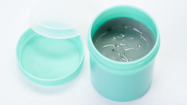
Lead-free solder pasteCommon problems in the printing process? Solder paste printing. First, check whether the parameter Settings of the solder paste printer are correct.PCBAll the solder paste is printed on the pad. Whether the height of the solder paste is uniform or in a "trapezoidal" shape, the edge of the solder paste should not have rounded corners or a collapsed pile shape. In the flow back soldering process of surface mount mounting, the solder paste is used to connect the pins or terminals of surface mount components with the middle of the solder layer. During the solder paste printing process, the substrate is placed on the worktable and held and positioned by mechanical equipment or vacuum pumps, with positioning pins or visual effects used for pointing. Either a wire mesh or a template is used for solder paste printing. This article will mainly discuss several important solder paste printing challenges, such as template design schemes and the entire printing process. Now, let's take a look at some common problems encountered by the editor of JJY.
Lead-free solder paste
:
Printing processing technology flow and machinery and equipment
Throughout the entire process of solder paste printing, the printing machine plays a crucial role in achieving the desired printing quality. Today, the screen printing machines available for purchase are divided into two key types: laboratory and manufacturing. Each type is further classified, as each enterprise expects to obtain different functional levels from the printing machines of the laboratory and production manufacturing types.
In handcrafted or fully automatic printing machines, solder paste is handcrafted and placed on the template/On the metal wire mesh, at this time, the printing scraper is at the other end of the template. In a fully automatic printing press, solder paste is distributed automatically. During the entire printing process, the printing scraper applies low pressure to the template, causing the bottom edge of the template to touch the top of the line board wall. When the scraper passes over the entire etched pattern area, the solder paste is according to the template/The perforations on the metal wire mesh are printed onto the welding layer.
After the solder paste had already accumulated, the wire mesh immediately loosened after the scraper and returned to its original position. This spacing or the loose spacing is determined by the design of the mechanical equipment, approximately0.020'~0.040'. The loosening spacing and the working pressure of the scraper are2A key independent variable related to facilities for achieving excellent printing quality.
If it is not loosened, this step is called touch printing. When applying metal shell templates and scrapers, touch printing should be used. Non-contact printing is used for soft metal wire mesh products.
Type of scraper
The damage, working pressure and strength of the scraper determine the printing quality and should be carefully inspected. For acceptable printing quality, the edge of the scraper should be sharp and parallel. Low scraper working pressure leads to ignored and rough edges, while high scraper working pressure or very loose scraper will cause patchy printing, and there is even a high possibility of damaging the scraper and the template or metal wire mesh. Excessive burden also tends to dig out solder paste from light openings, resulting in insufficient arc of the solder wire. There are generally two types of scrapers: vulcanized rubber or polyurethane material scrapers and metal material scrapers. When applying vulcanized rubber scrapers, the application70-90The scraper of the rubber hardness tester for strength. When an excessive burden is applied, the solder paste that penetrates to the bottom of the template is very likely to cause a solder bridge. It is stipulated that the bottom should be wiped frequently. To better prevent bottom penetration, the weld layer opening needs to be given a sealing effect during printing. This lies in the surface roughness of the opening wall of the template.
Metal material scrapers are also commonly used. With the application of denser spaced components, the usage of metal material scrapers is increasing. They are made of stainless steel plates or purple copper, with a flat blade shape, and the printing Angle applied is30~45°. Some scrapers are coated with lubricating raw materials. Due to the application of lower working pressure, they are not easy to dig out solder paste from the opening. Also, as they are made of metal materials, they are not as easily damaged as vulcanized rubber scrapers and thus do not need to be sharpened. They are much more expensive than vulcanized rubber scrapers and may cause damage to the template.
Different types of scrapers should be applied in the installation of printed power circuits using standard components and close-pin components(PCA)There is a difference between them. The regulations on solder paste quantity vary significantly for each type of component. The amount of solder wire required for closely spaced components is much less than that for standard surface mount components. The total area and thickness of the solder coating control the amount of solder paste.
Some technical engineers apply double-thickness templates to use an appropriate total amount of solder paste for close-pin components and standard surface mount solder layers. Other technical engineers choose a different way -They use more economical metal material scrapers that are not often sharp. It is much easier to avoid using metal material scrapers The change in the amount of solder paste accumulation, but these methods stipulate an improved template opening design scheme to avoid it There is too much solder paste accumulation on the closely spaced solder layer. This method is more favored in industrial production, but the use of double-thickness printed vulcanized rubber scrapers has not yet faded away.
Types of templates
The key independent variables of printing quality include the accuracy and smoothness of the template hole walls. It is crucial to have a reasonable aspect ratio of the total width and thickness of the storage template. The strongly recommended aspect ratio is1.5. This is for avoiding Template blockage is the key. Generally, if the aspect ratio is lower than1.5The solder paste will remain in the opening. Apart from the aspect ratio, such asIPC-7525What is suggested in the "Template Design Scheme Manual" still needs to be exceeded0.66The range ratio(The total area of the welding layer is divided by the total area of the hole wall).IPC-7525It can serve as a good start for the template design scheme. The processing technology for making openings manages the smoothness and precision of the opening wall. There are three common processing techniques for making templates: chemical etching, fiber laser cutting and additive processing.
Chemical corrosion template
Metal material templates and soft metal material templates are adopted2This positive pattern is etched and processed by organic chemical grinding on both sides. In this stage, the etching process is carried out not only at the desired vertical Angle but also horizontally. This is called dichotomy-The opening was larger than expected, resulting in the accumulation of additional solder wires. Because50/50Etching processing is carried out from both sides, and the effect is that the hole walls are basically parallel lines, with a slight hourglass-shaped drop in the middle.
Since the wall of the template hole processed by electro-etching is very likely to be not smooth, electro-polishing, a micro-etching, is a way to achieve a smooth wall . Another way to achieve a smoother hole wall is to electroplate a nickel layer. Grinding and polishing or a smooth surface is good for the application of solder paste, but it is very likely to cause the solder paste to flip over the surface of the template without flipping before the scraper. This problem can be prevented by selectively grinding and polishing the hole walls instead of the entire surface layer of the template. Electroplating nickel further improves the smoothness and printing characteristics. However, it reduces the number of openings and stipulates the adjustment of the pattern
Fiber laser cutting template
Fiber laser cutting is another processing technique, but it does not have the problem of undercutting. Template immediately fromGerberData information production has thus improved the precision of hole opening. Data and information can be provided as necessary Adjust to change the specifications. Stronger process management will also improve the precision of hole opening. Another feature of the fiber laser cutting template is that the hole wall can be conical. The template for organic chemical etching processing can also be conical. If etching is only done from one side, the opening size is likely to be very large. The surface opening is a slightly larger conical opening than that of the scraper surface(0.001'~0.002'Cause approximately2°The perspective)It is much easier to release the solder paste.
Fiber laser cutting can Produce the smallest0.004'The total width of the openings and the precision have been achieved0.0005'Therefore, it is very suitable for the printing of components with ultra-close intervals. The template of fiber laser cutting can also cause rough edges because the alloy vaporized during the laser cutting period turns into metal material slag. This will cause the solder paste to clog. Smoother hole walls can be achieved through micro-etching processing. The template for fiber laser cutting must not be calibrated in advance In thinner areas where chemical corrosion is carried out, stepped multi-level formwork cannot be made. The laser cuts each opening one by one, so the cost of the template is determined by the total number of openings cut by the laser.
Electroforming formwork
The third processing technique for making templates is an additive processing technique, widely known as electroforming. In this processing technology, nickel is deposited in the core of the copper anode to create openings. A kind of photosensitive dry film is stacked on a copper-clad laminate(Probably0.25'Thickness). The ultraviolet rays on the film are concentrated according to the light-blocking film with a template pattern design. After passing through the developer, the negative electrode pattern design is formed in the copper core, with only the template holes maintained and covered by photolithography technology. Subsequently, templates were produced around the photolithography technology based on electroplated nickel. After achieving the desired thickness of the template, remove the photolithography technology from the opening. The nickel foil formed by electroforming is separated from the copper core according to bending-A core technical process. Now the foil is ready for framing and the other processes of making the template.
As mentioned above, leaded processing has better weldability than lead-free processing, but lead-free processing is more environmentally conscious. Want to know aboutSMTFor other issues regarding solder paste in surface mount technology, partners are welcome to consult. Let's learn and grow together with Shenzhen JJY Industrial Technology Co., LTD.!


